RC Baja Suspension and Steering
Introduction
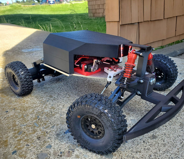
This project is focused on the suspension and steering components of an RC Baja vehicle. The focal point of this project is designing a suspension system that can handle large vertical loads or impacts from drops. This is inspired by the desire to make vehicles that can traverse difficult terrain in the hopes to apply to search and rescue vehicles. It is incredibly important to make a vehicle that will handle these loads and impacts without causing harm to the passengers or cargo or cause breakage throughout the components of the suspension or steering systems.
The suspension system is simple but will allow for a range in motion vertically by positioning the arms at a 30° angle downwards. This positions the body well above the ground to keep it safe and will give the arms approximately 45° of vertical motion before the body comes close to the ground. This design will allow for large drops and heavy loads compared to the weight of the vehicle.

Front Suspension System

Rear Suspension System

Steering
System
Results
The vehicle was subject to different tests to determine the reliability of the vehicle's suspension and steering. The first test was a drop test where the vehicle was dropped at increasing heights to determine the spring constant and maximum height before the vehicle bottoms out. It was determined that the vehicle bottoms out and heights over 1' and a spring constant average was calculated to be 44.7 lbf/in. The next test was a deflection test to test the component that is the weakest and experiences the most force, the upper control arm. This test was performed using an instrom device to slowly add force to the component and measure its deflection. Two trials were run of this test and the component deflected 0.0318" with a load of 34lb and 0.0412" with a load of 57lb.
This project has experienced a large amount of changes since its start. Since it uses a lot of 3D printed parts, it is difficult to do accurate calculations on the components and how they will truly act under the forces. With that said, the components are performing better than calculated values. The drop test was a failure because the shocks are not sold by their spring constant so it is a guessing game when purchasing them. However, despite this, the project is successful in meeting most of its requirements. The 3D printed components are strong enough to not deform or break with all of the forces with an exception being a direct impact at high speeds.
The vehicles last test was to look at the turn angles of the vehicle and compare it to the required turn angle to meet the requirement of making a 180° turn in a 3.5' radius. The required turn angle of the tire for this turn was calculated to be 19°. The vehicle had a minimum turn angle for the tires of 4°, substantially lower than the required turn angle. This test showed that the vehicle requires redesign of the steering system in order to achieve the desired turn radius.